Wow, what can I say? My first AU was very awesome! It was held at The Venetian in Las Vegas, NV during the last week of November. The Civil 3D and Map 3D sessions that I attended were all very good and I learned at least one new trick in each class. Some classes were somewhat overwhelming in what and how much information was shown and when those type of classes were held back-to-back-to-back, well, I just had to take a break and recoop my thoughts at the blackjack table ;-). All good information though and you would think an hour-and-half for a session would be more than adequate, but some sessions could have easily been half a day. But I understand the general premise, wet the appetite so you come back for more. And also to get folks energized, creating, and figuring things out on their own.
I highly recommend attending Autodesk University at least once. If you haven't been before, you are missing out. If your company has a yearly budget for training, have them set some extra $$$ aside for next year to send you or one of your work buddies (or preferrbly send everyone if they can afford it :-0 ). You will more than likely get a high return on your investment. All of the presenters were very enthusiastic and passionate about their particular topic, and it showed through during their lectures. Everyone was very helpful after the sessions too by fielding and answering questions. I actually kept a couple of the Autodesk GIS experts from having lunch on-time after the "Map 3D for Civil 3D Users" class because I had a few "innocent" questions for them (sorry Mark and Brad - thanks again for your time).
I am pretty motivated after this conference to get things rolling and back on-track at my office concerning Civil 3D, not that we are that far off. I'd conservatively estimate that our Civil department staff is in the top 20% among current Civil 3D users worldwide. I don't how I exactly quantify that; its just my gut feeling after speaking with people from other firms and seeing where they are at in the implementation process. But more can be done at Clark Nexsen to standardize and implement... much more. Some of our Civil 3D project tasks include continuing to generate DTM surfaces, from which we perform grading and earthwork calculations, and generating profiles and cross-sections for site analysis. We have started to develop storm drainage, sanitary sewer, and water distribution Pipe Networks on a few of our projects and are looking for ways to mesh the Hydrology & Hydrualics design in as part of this process (got some great ideas on this at AU). And our Transportation department is having nice success using Corridor modeling to develop roadways, especially after Service Pack 3 was released (thanks Autodesk!).
The process workflow has been a natural progression from Land Desktop for our more experienced users. And the process should be easy enough for new users who do not carry along all of the old DCA / Softdesk / Land Desktop baggage like some of us old dinosaurs (hey now... I'm not 40 just yet!). I believe we are now just starting to get into a rhythm with our C3D design workflow...and all without Vault too! (thanks again Autodesk for fixing Data Shortcuts in SP3 - works like a CHAMP!)
I personally am more confident about my knowledge level and capabilites after attending AU. I've been in the industry for 20 years and new technologies never ever cease to amaze me. While meeting other users, I saw we are certainly not alone in our successes, failures, and wishes - we are all in this together. This is another part of the AU conference that was invaluable; meeting your peers and sharing experiences to better ourselves and letting software developers know the tools we need today to do our work. And not just to do our work, but to complete our projects accurately and efficiently, while having fun in the process.
One day someone will end up developing the "Do Project" button, where you click on the "Do Project" icon on your Windows Desktop, it starts running some sort of script in the background while you, with your headset on, verbally tell the computer some basic information about your project, AutoCAD opens along with a variety of other softwares in some sort of weird but well-thought-out design sequence, designs and drafts the job for you, creates a sheet set DWF, then asks you to which printer would you like to print your final drawings... and VOILA! - your project is complete, start to finish - one button. Yeah right, keep dreaming!
Oh yeah, one more thing I learned at AU - Don't hit on 18! A-2-5 totals 8, but also totals 18. All I saw at the time was 8 (one too many free drinks). What an idiot I am! But believe it or not I got away with it that time.
Wednesday, December 06, 2006
Monday, November 06, 2006
Pond Volumes - Don't forget to "INFILL"
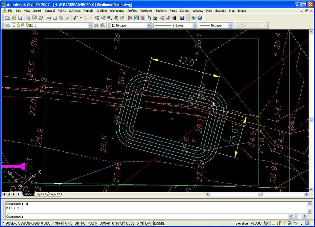
Calculating volumes for ponds and sediment traps is even easier now with the new grading utilities in Civil 3D. But if you're an experienced Land Desktop user, the grading objects do not react quite like they used to. Be careful not to leave out the surface definition for the bottom of the pond. In Land Desktop, the grading objects defined TIN lines for the pond bottom for you. LDT objects connected the TIN at the bottom. Civil 3D gradings may not depending upon how they are defined. For instance, look at this example.
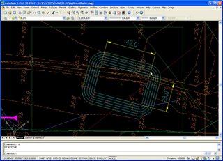
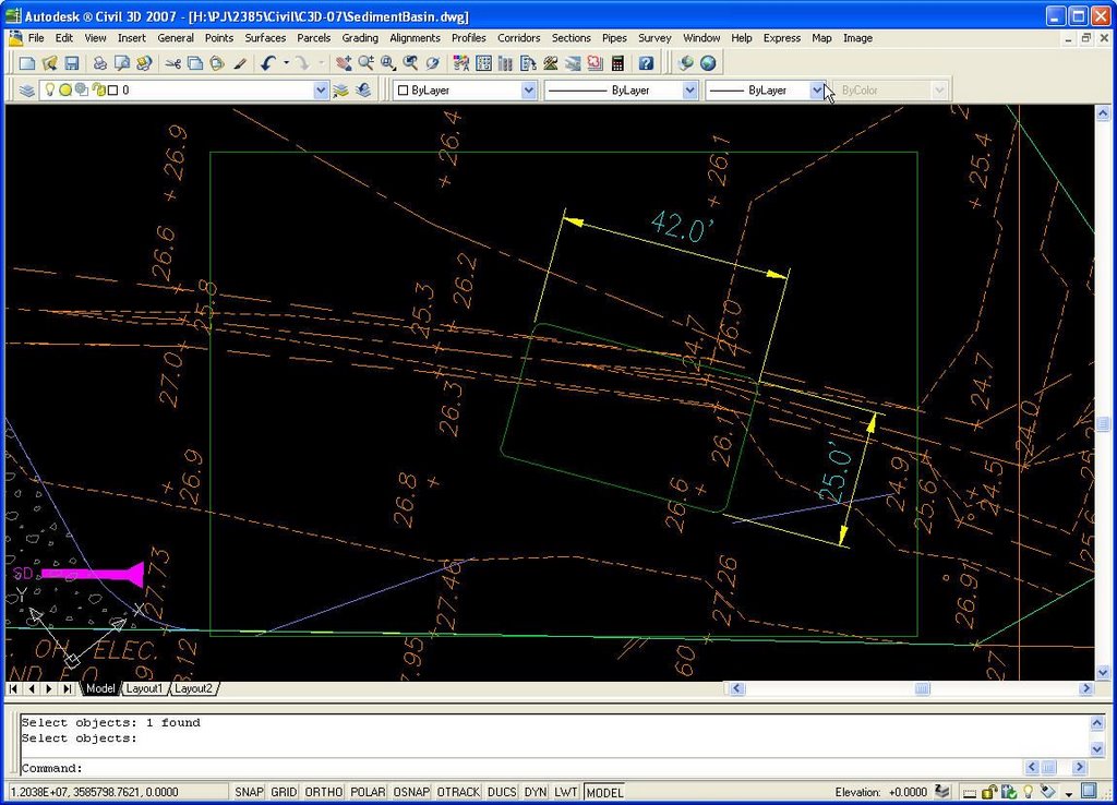
Here we have defined our pond bottom as a 42' x 25' rectangular feature line set at elevation 20.0'.
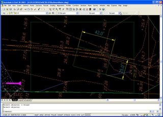
Then we add a grading with 2:1 slopes up to elevation 25.0'. The grading will automatically create my surface "SedBasin".
Also, define a surface called "Storage" by using a rectangular feature line and set it's elevation to 25.0'(see the green rectangle surrounding the pond in the previous view). This will give you a comparison surface for volume calculation.
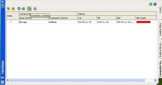
Then calculate your pond volume (located in the 'Surfaces' pull-down menu, Utilities --> Volumes...).
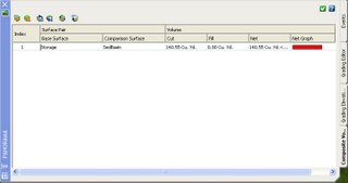
About 140 CY of storage, great. But wait. Let's manually check this.
Our pond bottom is roughly 42' x 25', or 1050 SF. Using the 2:1 slope, the pond top is roughly 62' x 45', or 2790 SF. The average surface area is [(1050 + 2790) / 2], or 1920 SF. A pond 5 feet deep like ours should have an estimated volume of around 1920 SF X 5 Feet = 9,600 CF, or about 356 CY. Well this does not compare with our volume from Civil 3D! What happen? We did not "Infill" the bottom of the pond, therefore there is a hole from the bottom to the top of the pond within the bottom surface area. Only the area within the side slopes is being calculated.
Let's correct.
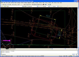
Use the "Create Infill" option to create a pond bottom infill
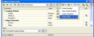
and Select a point inside the pond. The Infill is represented by the Green diamond symbol within the center of the pond.
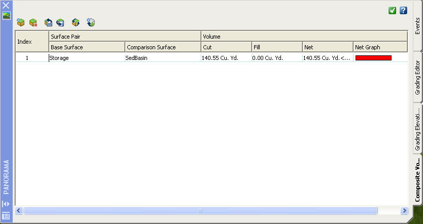
Now use the "Refresh" button to update the pond volume
Now we're cooking! 334 CY compares favorably with our manual calculation of 355 CY.
Now if you need stage volumes at elevations 21, 22, 23, and 24, then just revise the elevation of the feature line which defines the "Storage" surface using the "Feature Line Editor" and "Refresh" the volume each time you change the stage elevation. The "Cut" volume will be your storage volume at that elevation. The "Fill" volume may be ignored for this calculation.
Here we have defined our pond bottom as a 42' x 25' rectangular feature line set at elevation 20.0'.
Then we add a grading with 2:1 slopes up to elevation 25.0'. The grading will automatically create my surface "SedBasin".

Also, define a surface called "Storage" by using a rectangular feature line and set it's elevation to 25.0'(see the green rectangle surrounding the pond in the previous view). This will give you a comparison surface for volume calculation.
Then calculate your pond volume (located in the 'Surfaces' pull-down menu, Utilities --> Volumes...).
About 140 CY of storage, great. But wait. Let's manually check this.
Our pond bottom is roughly 42' x 25', or 1050 SF. Using the 2:1 slope, the pond top is roughly 62' x 45', or 2790 SF. The average surface area is [(1050 + 2790) / 2], or 1920 SF. A pond 5 feet deep like ours should have an estimated volume of around 1920 SF X 5 Feet = 9,600 CF, or about 356 CY. Well this does not compare with our volume from Civil 3D! What happen? We did not "Infill" the bottom of the pond, therefore there is a hole from the bottom to the top of the pond within the bottom surface area. Only the area within the side slopes is being calculated.
Let's correct.
Use the "Create Infill" option to create a pond bottom infill

and Select a point inside the pond. The Infill is represented by the Green diamond symbol within the center of the pond.
Now use the "Refresh" button to update the pond volume

Now we're cooking! 334 CY compares favorably with our manual calculation of 355 CY.
Now if you need stage volumes at elevations 21, 22, 23, and 24, then just revise the elevation of the feature line which defines the "Storage" surface using the "Feature Line Editor" and "Refresh" the volume each time you change the stage elevation. The "Cut" volume will be your storage volume at that elevation. The "Fill" volume may be ignored for this calculation.
Tuesday, October 03, 2006
Data Shortcuts Revisited
Civil 3D life sure is tough when you don't have the tools to properly do data management. At least that's the way I see it in the life outside of Autodesk Vault. Our company has been holding off on implementing Vault until we see what becomes of it. There had been some rumors about Vault being implemented as part of a future release of Revit Building. That would have gotten our Architectural department fired up about Vault and would have certainly started the ball rolling towards purchasing the required hardware and software (Windows server, MQSQL server, etc., etc.) required to run a corporate-wide Vault system. But now as it stands, the Revit / Vault tie-in seems unlikely to happen. So needless to say, data management has been virtually non-existent for us in the Civil 3D world. Sharing data in Land Desktop was cumbersome enough. And "manually" trading LandXML files back-and-forth between our user base in my opinion is a step backwards and just doesn't make the cut. Yes it can be done, but there's got to be a better way (without Vault).
So back to the future. The good folks at Autodesk have decided to include a "not so old" favorite back into the their system - Data Shortcuts are BACK!!! Or at least they will be in the near future. Dan Philbrick of the Autodesk Civil 3D development team posted in his blog entry of 9/29/2006 that Data shortcuts will be reintroduced in an upcoming release. All I have to say in my best Napoleon Dynamite voice is, "Sweet!". This means that a method that we've been trying to use, as described in a post on Angel Espinoza's blog entitled Civil 3D 2007 - Data Shortcuts, will most likely work again in some form or fashion like it did in previous versions.
A Beta of the "Data Shortcuts enabled-version" is due to be released soon and will be available for download and testing to those who contact the Autodesk development team. Also, more details will be discussed during this Friday's C3D webcast (10/6/2006).
Tuesday, September 12, 2006
Q = ciA
Hopefully this will be one of the equations Autodesk solves for in their next release of Civil 3D. I'm telling you...wouldn't it be nice to be able to overlay land use information over drainage area polygons to extract weighed "C" values per basin? Then add in the terrain surface model to determine the most hydraulically distant point within each catchment area, the travel paths, and have the software figure out time of concentrations (Tc) for overland, shallow concentrated, and open channel sheet flow conditions. Then input rainfall amounts to determine flow amounts per area. Simple rational method calculations you know. Then have a print out in a nice LandXML formatted report. Now that my friends would be a huge step closer to the Holy Grail and would begin to make that second "D" in CADD grow just that much larger.
Oh BTW, I apologize for not posting more often. You folks who read the Civil 3D newsgroup may have seen a thread concerning the issues that I've been having with Service Pack 2 and the Pipes options. Unfortunately, I think my final answer is to wipe my system clean and start fresh with a clean Windows OS install. Go figure. And out of a few computers which have been upgraded at my office, mine is the only one not to work. Must be that mediaWiki install that I did a while back using Apache web server, PHP, and MySQL. C3D Pipes may have not liked that, but at this point, that is only a guess. It's pretty much the only thing I haven't uninstalled from the system to troubleshoot my Pipes problem. If I find out what is causing the issue, I'll post it here (and the newsgroup).
Oh BTW, I apologize for not posting more often. You folks who read the Civil 3D newsgroup may have seen a thread concerning the issues that I've been having with Service Pack 2 and the Pipes options. Unfortunately, I think my final answer is to wipe my system clean and start fresh with a clean Windows OS install. Go figure. And out of a few computers which have been upgraded at my office, mine is the only one not to work. Must be that mediaWiki install that I did a while back using Apache web server, PHP, and MySQL. C3D Pipes may have not liked that, but at this point, that is only a guess. It's pretty much the only thing I haven't uninstalled from the system to troubleshoot my Pipes problem. If I find out what is causing the issue, I'll post it here (and the newsgroup).
Tuesday, August 01, 2006
Revit Civil?
I saw a demonstration of Revit Building today by one of our Electrical designers and I got to thinking; why don't the Architectural / Building Systems and Civil software developers at Autodesk coordinate more with each other? Revit has a pretty slick user interface and I could definitely see working with Civil 3D in that environment.
Also, it would seem like Autodesk would want to streamline their building and infrastructure product lines into one system: Revit Building, Revit Structure, Revit Systems, and of course "Revit Site" could replace Civil 3D.
Civil engineers would not be the only ones who would benefit. Electrical and Mechanical engineering types also have design elements related to site work - lighting, power and commuications ductbanks, gas mains, steam lines just to name a few. The Civil techs usually "get stuck" with doing the electrical and mechanical site work, especially developing profiles, because they are the ones who are most familar with working with site plans. Why not share the wealth by extending this functionality into Revit, and therefore somewhat merging the projects so they are more compatible?
Architects could also use the site model from "Revit Site" to perform 3D visualizations and analysis in a more compatible, flexible, and "coordinated" environment. (emphasis here on the use of "coordinate" d ).
I was impressed by the features of Revit from what I saw in the brief demo. I believe it could most definitely translate over to the Civil side. If you ever get the chance to attend a Revit seminar, I'd highly recommended it, if only just to see want the "other side" is up to.
Tuesday, July 25, 2006
CIVIL 3D ROCKS: Eliminating the "Pseudo Sump" on Structures Civil 3D 2006 and 2007
Here's how to remove an unwanted sump within a structure by creating and setting a floor thickness equal to 0.
CIVIL 3D ROCKS: Eliminating the "Pseudo Sump" on Structures Civil 3D 2006 and 2007
CIVIL 3D ROCKS: Eliminating the "Pseudo Sump" on Structures Civil 3D 2006 and 2007
Monday, July 24, 2006
Civil 3D update
Our Civil 3D implementation is progressing here at Clark Nexsen. We are slated to have 20 members from our Civil Engineering department trained on the product by an outside consulting firm, Inlet Technology, near the end of August. Should be interesting. In the meantime, I've been using the software with success on a couple of large grading projects for the U.S. Army Corps of Engineers. I've found a couple of bugs/issues which Autodesk promptly helped me with through the use of the Civil 3D newsgroups. Thanks Autodesk!
Also, trying to get the styles created for our Imperial and Metric templates. It's a slow process when you really don't have time for it and projects have deadlines which are more important. Gotta' pay the bills. Anyway, we're getting there.
Also, trying to get the styles created for our Imperial and Metric templates. It's a slow process when you really don't have time for it and projects have deadlines which are more important. Gotta' pay the bills. Anyway, we're getting there.
Thursday, June 15, 2006
Wednesday, June 07, 2006
Grading objects as Surface Breaklines
Did you know that you can add grading objects to a surface by adding them as breaklines? It works! You can also add feature lines as breaklines to surfaces too. Pretty cool! I think this only works in C3D 2007 though, so you will need to upgrade if you haven't done so already.
Tuesday, May 23, 2006
Now you don't see it, now you do!
This is classic AutoCAD. OK, so a few days ago I was using Civil 3D 2007 to layout some storm drains and create profiles. Well, as you might know, you can now have background masking as part of the object labels. I have installed C3D 2007 on my computer and a couple of other users machines but we have not rolled out the product completely, so any designs that are done in 2007 format have to be converted back to AutoCAD 2004 format so anyone else can work with the drawing files.
So everything works well with my design and it's time to save and "Export as 2004 format". No problem. Did the export and let the CADD technician I was working with know that the drawing was ready to be setup in the Grading and Drainage Plan for printing. Everything is working great, drawing looks fine on the screen, even the background masking is working! The technician comes back to me about 15 minutes later, with a puzzled look, and was telling me that the text was printing out as black blobs. What? How could this be? It looks fine on the screen. "Must be the plotter", I thought. We've seen this problem before and it had to do with the print driver, or, was it the dreaded Wipeout plot issue resurfacing. OH NO!!!
We sat down together at his desk and looked at the drawing. Looked fine. Looked at the print preview, black blobs where the text labels were. Hmmmmmmm... "Let's do a crossing on the text to see what's there", I asked. Did the selection crossing and low and behold there appears to be a selectable, invisible, rectangular object behind the text; 2 objects selected. Now mind you, we maintain a black background within the drawing space for both paper space and model space for all of our AutoCAD configurations.
We listed the entity in question and it lists as a Solid HATCH with a color of "0,0,0", or black. What??? We changed the drawing space background temporarily to "White" and sure enough there were black, Solid, hatches behind every text label that had been defined with a background mask in Civil 3D 2007. During the conversion process, AutoCAD converted all background masks to a solid, black hatch. Too funny!!!
The fix was easy. We just "FILTER"ed out all hatches on that layer and erased them. But now we have to repeat this step everytime we use the "Export to 2004..." option. I tell you, it's always something, huh?
Monday, May 15, 2006
Thanks Angel!
Thanks to Angel Espinoza for the blog entry on his site and the link to my blog. As I recall, his site was one of the first blogs dedicated to Civil 3D and continues to be one of the most informative out there. I definitely have a RSS watch out on Angel's blog for new entries because he always has something very useful posted. Keep it up Angel and I'll try to do the same.
Tuesday, May 09, 2006
Civil 3D 2007 Initial Thoughts
Ok, I installed Civil 3D 2007 last Thursday and have been using it on one of our new projects. Did not install Vault, looks too complicated. Plus I'm in it for the design features not the database management. All is going pretty good so far. The product is not as stable as 2006 though; a lot of crashes and fatal errors. Probably about 6 to 8 during the course of my work yesterday. And RECOVER does not work well. I usually lose about 50% of my drawing objects when I am able to recover. Not good. And unfortunately the system crashes are random and cannot be recreated. A couple of times Civil 3D crashed when doing an automatic save. That was frustrating. Auto save usually works so I've set it to 5 minutes just because. Normally I'd set it to 15 to 20 minutes. I use QSAVE when I remember too also.
Overall though, I think it's still worth installing and using just because of the new functionality. I can look beyond the short-comings at this point. The grading design I just did in C3D 2007 was pretty easy to develop. I say I was able to complete the design in about half of the time it would have taken me in Land Desktop. The automatic surface rebuild feature allows you to see the contours change as grading features are added to the surface. You could do this in previous versions of C3D but the rebuild seems much, much faster now.
Well, back to it. I've learned much in the past few days which I will try to share here. So check in every so often.
Tuesday, March 28, 2006
Having Weird Profile Results?
If you have an existing profile grade line that just doesn't want to be drawn in at the correct elevation in places along your alignment, then check the existing surface for 0.00 elevation points. 0.00 surface elevations can cause erratic results in the profile view even if the 0.00 elevations are outside your corridor area.
There are a few ways to check for 0.00 elevations in a surface. The one I like is to turn ON the TIN lines, then use 'VPOINT' command to view the surface TIN in 3D. You can also edit or delete those points within the 3D VPoint view. Once the surface has been fixed, use command 'PLAN' to return to "2D" plan view.
There are a few ways to check for 0.00 elevations in a surface. The one I like is to turn ON the TIN lines, then use 'VPOINT' command to view the surface TIN in 3D. You can also edit or delete those points within the 3D VPoint view. Once the surface has been fixed, use command 'PLAN' to return to "2D" plan view.
Wednesday, March 01, 2006
Initial Post
Yep, that's right. DCA to and through Civil 3D 2007, including side excursions into Eagle Point, IGrds, and CAiCE with maybe a little bit of GeoPAK and INRoads thrown in for good measure. If you've read this far then you probably know what I'm going to be blogging about - my continuing journey into AutoCAD-related Civil Engineering design softwares. Oh, and don't forget those GIS programs, ArcView and AutoCAD Map because they can be an engineers secret weapon when the going gets tough.
So jump in the back, hang on, and let's go for a ride. In the words of legendary boxing referee Judge Mills Lane, "Let's get it on!".
So jump in the back, hang on, and let's go for a ride. In the words of legendary boxing referee Judge Mills Lane, "Let's get it on!".
Subscribe to:
Posts (Atom)